When I started working in the spring industry, most of my exposure was with round wire. Round cross-section tends to behave more predictably than other wire shapes. When I started in Engineering, I had to face all different scenarios.
One of the more interesting phases was my stint as a ring engineer. I had no clue that a piece of wire in the form of a circle could have so many potential challenges.
One of those challenges was the reality of “upset.” When square or rectangular shaped wire is coiled into a ring, pressure is put against the ID as the ring is formed. And even though the material may be spring temper, it still deforms.
This deformation or growth is called “upset.” This means the size of the wire on the ID has now increased. This could or could not be an issue. For rings, it typically is a concern.
This is because rings, especially snap rings, are placed into grooves to hold something in place. If the wire is rolled or purchased to a specified size, but then increases during forming, it may not fit into the groove. The cross-section is no longer rectangular after upset—it is trapezoidal.
Also, the ring index is important. The index is the ratio between the mean diameter and material width—it’s an indicator that clues us into just how tightly the ring is wound.
Small indices mean more pressure is being put on the wire as it’s formed and more upset will occur. Large indices have very little upset and are usually not a problem.
If the upset is substantial, the only way to hold a tolerance on the material thickness is to grind the ring and remove all the upset material. Grinding will increase the cost, but is not an option if there is any precision involved in the application. Many snap ring applications for automotive and ag require ±0.001″ tolerance. Grinding must be performed to create the needed precision. This also means the engineer must know how much upset will occur and compensate by calculating additional material to be removed during grinding. In my experience, this was at least 0.015″ additional material to be sure the entire ring surface is ground without missed spots that cause variation, in more recent experience, die springs take center stage.
Most die springs are made from rectangular shaped wire and have small indices. This means the material upset can be substantial during coiling.
The result is solid heights that are considerably greater than what is calculated on just the purchased material thickness.
For example, a die spring could have a material cross section of 0.250″ X 0.375″. After coiling, the 0.250″ cross section could upset to 0.267″ on the inside diameter. This is an additional 0.017″ for each coil. If the spring has 12.3 total coils, the theoretical solid height calculation would be 12.3 x 0.250″, or 3.075″. But, with the material upset, the actual solid height will be 12.3 x 0.267″, or 3.284″ (Figure 1). The spring has just lost 0.209″ potential deflection due to upset alone—not a small discrepancy since compression-style springs are designed for the most deflection before set.
This upset must be known for the spring designer to create proper designs without huge losses in deflection potential.
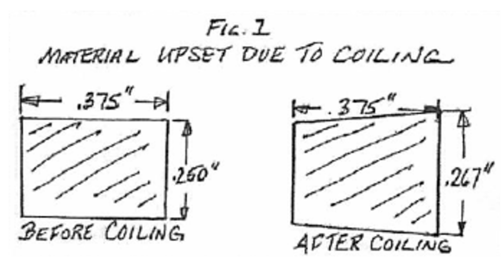
Figure 1
For die spring makers, the answer to the upset issue is to purchase keystoned material that will upset into the proper thickness, or at least very close. This is an example of how the process of springmaking itself can add variation that must be predicted and compensated before hitting the shop floor.
Spring Fundamentals…
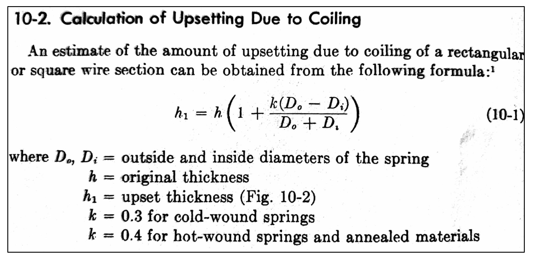
Calculation for upset by Dr. Wahl, taken from page 126 of Practical Design of Helical Compression and Extension Springs:
By: Randy DeFord, Engineering Manager Mid-West Spring & Stamping