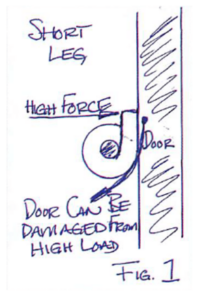
Figure 1
But torsion springs provide forces based on torque. That means the calculations are producing inch-lbs or foot-lbs, not just pounds. So, this scheme is predicated by the fact that forces produced by the legs of a torsion spring are completely dependent on where on the leg a force is applied. A great deal of my exposure to torsion spring applications is with the RV and trailer industry. Being located in northern Indiana, that part of the country is known for industries that produce a lot of trailer products, for people, horses and other various produce cartage.
The standard approach, that works very well, is to thread a number of torsion springs along a rod at the bottom of the trailer door…an array as it were. One of the complaints I have heard over the years is that the door, whether wood, aluminum or otherwise, is being masticated by the torsion spring leg. In all cases, this is because the leg is short and the loads on short torsion legs are very high.
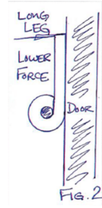
Figure 2
Also, torsion spring legs tend to move along their mating door and will scrape and otherwise distort anything they contact. Since the springs are made from hard alloys, the door gets punished (Fig.1).
There are, however, solutions to this problem. One fix is to put a 1/4″ thick strip of steel along the length of the trailer door where the torsion legs make contact.
This reinforcement will shield the door from the high load of the short torsion leg. The other approach is to lengthen the torsion leg and be sure the door is contacting the spring leg near the end. The forces are much less as you move away from the spring body. Since the spring rate is in the body and not the legs, the rate will stay constant.
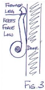
Figure 3
But the force required to rotate a torsion spring is less with a longer leg since the legs follow standard moment theory – leverage. The farther out of the leg you push, the less force is required to push the spring an equivalent degree of rotation. Taking advantage of the longer leg can reduce the forces applied to the mating door and solve the problem with little cost (Fig. 2). It is also possible to form the spring leg to assure contact is only made by the tip of the leg and this only allows the lowest force to be applied to the door (Fig. 3).
Spring Fundamentals…
Free Length After Deflection Calculation
When calculating torsion springs, it’s essential that the free length after deflection be calculated.
When torsion springs rotate, the free length increases. If this is not considered when designing, the length increase could cause major failure. The first calculation is the increase in coils due to deflection.
This would be N’ = N + (deflection / 360), with N being the number of active coils.
Then to determine the new total free length with deflection, we have:
FL’ = (N’+1) X(wire size or axial width)
By: Randy DeFord, Engineering Manager Mid-West Spring & Stamping